EN50160 Power Quality Analyzer
IEC 62053-22
EN 61000-4-2
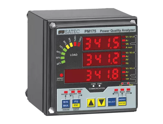
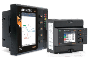
The PM175 is an analyzer providing the full range of power quality monitoring and reporting, according to the EN50160 standard.*
Equipped with built-in digital I/Os and a serial communication interface supporting SCADA-driven protocols, it is suitable for integration in utility substation or industrial SCADA systems. Its powerful LED 7-segment display shines visibly in the darkest environments, facilitating a quick reading of crucial power parameters on-site. Likewise, it is equipped with a LED load-bar, enabling the...
| Accuracy | |
|---|---|
| Class 0.2S per IEC 62053-22 | |
| Class 0.2 per IEC 61557-12 | |
| Power Meter | |
|---|---|
| Power: True RMS volts, amps, power, power factor, neutral current, angles and unbalance for voltage and current, frequency, symmetrical components and many more | |
| Event and parameter data-logging | |
| Sampling frequency: 128 samples per cycle | |
| Power Quality | |
|---|---|
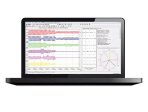
| EN50160 / GOST 32144 monitoring, statistics & reports | |
| Event statistics complimented by waveform recording | |
| in 6 channels (3 voltage inputs, 3 current inputs) @ 128 samples/cycle | |
| Voltage and current harmonics and THD coefficients up to the 50th order harmonic | |
| Directional power harmonics | |
| Flicker according to IEC 61000-4-15 | |
| Data Logger | |
|---|---|
| Time-of-Use (TOU), 8 totalization and tariff energy/demand registers x 8 tariffs, 4 seasons x 4 types of days, 8 tariff changes per day, easy programmable tariff schedule | |
| Event recorder for logging internal diagnostic events and setup changes | |
| 16 data recorders; programmable data logs on a periodic basis and on any internal and external trigger | |
| Variable Current Inputs | |
|---|---|
| 5A | |
| 1A | |
| HACS: special 40mA inputs for SATEC’s High Accuracy Current Sensors | |
| RS5: special 5A input for 5A clip-on HACS for retrofit installation on existing MV/HV CT secondary. | |
| ABB Sensor Interface (see below) | |
| Voltage Measurement Inputs | |
|---|---|
| Available options: |
|
| 120V AC Nominal voltage | |
| 690V AC Nominal voltage |
| Built-in I/O | |
|---|---|
| 2 Digital Outputs: 3A/250 VAC; 3A/30 VDC; 2 contacts (SPST Form A) | |
| 2 Digital Inputs: (dry contact; 15V Internal power supply) | |
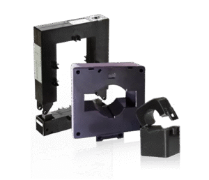
| ABB MV Sensor Interface | |
|---|---|
| These sensors are compatible with MV power systems rated up to 24kV. Specific sensors tested by ABB for compatibility with the PM174 in the following current ranges: | |
| 20-650A | |
| 200-4,000A | |
| Current sensors | |
| Type KECA 80 Cxxx (C104, C165, C184, C216, C260) | |
| KECA 80 C85/td> | |
| KECA 80 D85 | |
| Voltage sensors | |
| type KEVA 17,5B20, 5B21 | |
| type KEVA 24B20, 24B21 | |
| type KEVA 24C10, 24C21, 24C22, 24C23, 24C24, 24C25, 24C26, 24C30 | |
| type KEVA 24C10c 24C21c, 24C22c, 24C23c, 24C24c, 24C25c, 24C26c; “c” stands for Metal coated (conductive surface) | |
| KEVA 24C2 4.1 KEVA 24C2 4.1c; “c” stands for Metal coated (conductive surface) |
|
| Combined voltage and current sensors | |
| KEVCY 24 RE1 | |
| KEVCD A. Sensor name codes : KECVD 12 AE3, KEVCD 17.5 AE3 , KECVD 24 AE3. | |
| Communication interfaces | |
|---|---|
| Built-in | |
| RS-485 | |
| RS-232/422 | |
| Optional/additional: (1 per device): | |
| ETH 10/100Base-T | |
| PROFIBUS | |
| 2G/3G/4G modem | |
| Additional I/O | |
|---|---|
| 4 Digital I/O | |
| 2 Digital Inputs + 2 Digital Outputs | |
| 2 Analog Inputs available rating: | |
| ±1mA | |
| 0-20mA | |
| 0-1mA | |
| 4-20mA | |
| 2 Analog Outputs available rating: | |
| ±1mA | |
| 0-20mA | |
| 0-1mA | |
| 4-20mA | |
| 0-5mA | |
| ±5mA | |
| Programmable Logical Controller | |
|---|---|
| Embedded programmable controller | |
| 16 control set points; programmable thresholds and delays | |
| Relay output control (for alarm and protection) | |
| ½-cycle response time | |
| Display | |
|---|---|
| 3-row (2×4 characters + 1×6 characters) bright LED display, adjustable update time, auto-scroll option with adjustable page exposition time, auto-return to a default page |
|
| LED bar graph showing percent load with respect to user-definable nominal load current | |
| Detachable display module with a 3-wire RS-485 interface; up to 1000 meters operation | |
| Real Time Clock | |
|---|---|
| Built-in clock and calendar functions | |
| 2 year battery backup | |
| Communication Protocols | |
|---|---|
| Modbus | |
| ASCII | |
| DNP3.0 | |
| Profibus | |
| Power Supply | |
|---|---|
| 9.6-19V DC | |
| 19-37V DC | |
| 37-72V DC | |
| Meter Security | |
|---|---|
| 3 levels Password security for protecting meter setups and accumulated data from unauthorized changes | |
| Mounting | |
|---|---|
| 92X92mm square | |
| 4’’ round cutout | |
| DIN-rail mounting | |