per IEEE C37.118.1
IEEE C.37.118
IEEE 62055-118-7:2018
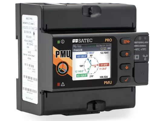
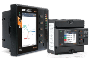
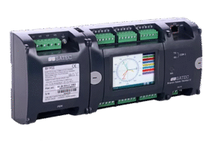
A Phasor Measurement Unit, or PMU for short, is the essential building block in the platform
called Wide Area Monitoring System (WAMS). These systems were developed to provide an overall
real-time health check of nation-wide transmission grids, predicting and helping to prevent
power failures, analyzing those which did take place.
By interfacing Global Positioning System (GPS) receivers or clocks, or using Precision Time...
| Phasor Measurement Unit | |
|---|---|
| IEEE C37.118.1-2011, IEEE C37.118.1a-2014 and IEC/IEEE 60255-118-1:2018 P-Class and M-class performance compliance | |
| IEEE C37.118.1 compliant three-phase voltage, current, and positive and negative sequence phasor measurements synchronized to a common UTC time reference | |
| IEEE C37.118.1 synchronous frequency and Rate of Change of Frequency (ROCOF) measurements | |
| Clock synchronization to a UTC time reference using an IRIG-B timecode source or an IEEE 1588 PTPv2 master clock source | |
| IEEE C37.118.2 commanded client-server UDP and TCP data transmission and spontaneous UDP data transmission over IP protocol | |
| IEEE C37.118.2 reporting rates from 1 to 200/240 frames/s | |
| Streaming of phasor data over Ethernet using the IEC 61850-9-2 multicast sampled value (SV) service with IEEE C37.118.2 compliant mapping of synchrophasor data upon IEC 61850-9-2 and IEC 61850-90-5 guidelines | |
| Expected steady-state total vector error (TVE) at nominal frequency: < 0.05% | |
| Streaming rate: 1 to 200 or 240 frames/s @ 50 or 60Hz, respectively | |
| IEEE C37.118.2 | |
| • Synchrophasor data frames transmit a time stamped set of measurements that include phasor estimates, frequency deviation from the nominal power line frequency or actual frequency, and the rate of change of frequency. | |
| • The data frame can be expanded to contain analog data (total active, reactive and apparent power, and power factor) and digital input status information. | |
| • Phasor components can include three voltage and three current phasors, positive sequence voltage and current phasors, negative sequence voltage and current phasors, or all of them in one frame. | |
| • Complex phasor values can be sent in a rectangular coordinates format (real and imaginary) or in polar coordinates (magnitude and angle). | |
| • Phasor and frequency data can be represented in 32-bit IEEE floating-point format or as 16-bit scaled integer numbers. When using the integer format, the data conversion factors are provided in IEEE C37.118.2 configuration frames. | |
| • Client-server UDP and TCP data transmission; spontaneous UDP data transmission over IP protocol | |
| • Optional IEEE C37.118.2 frame extensions with analog data (total active, reactive and apparent power and power factor) and digital status data (up to 32 inputs) | |
| • The PMU PRO supports CFG-1, CFG-2 and CFG-3 configuration frames. | |
| • In spontaneous UDP data transmission mode, CFG-2 or CFG-3 configuration frames can be sent spontaneously without an explicit user command. When enabled, a configuration frame is sent periodically every 30 seconds. | |
| 5 data streaming slots for continuous synchrophasor data streaming via unicast UDP or/and TCP connections | |
| Logging, Recording & Programming | |
|---|---|
| Programmable controller: up to 32 control setpoints and half-cycle scan time | |
| OR, AND, arithmetical functions logic, extensive triggers, programmable thresholds and delays, relay control, event-driven data recording | |
| Event recorder for logging internal diagnostic events, power faults and operations of the logic controller and digital I/O | |
| Eight data recorders with programmable datasets for data logging on a periodic basis and on any internal or external trigger | |
| 32 digital counters for counting internal events and pulses from external sources | |
| 16 interval timers with programmable periods from half cycle to 24 hours for periodic recording and triggering timed operations | |
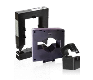
| Variable Current Inputs | |
|---|---|
| 5A | |
| 1A | |
| Voltage Measurement Inputs | |
|---|---|
| Measurement category: CAT III | |
| Operating range: up to 277/480 VAC +25% | |
| I/O | |
|---|---|
| Built-in I/O | |
| 1 AI (±1 mA; 0-1 mA; 0-20 mA; 4-20 mA) | |
| 1 SSR (100mA/250V AC/DC) | |
| External power supply 24/48/125/250V DC | |
| 1 DI | |
| Internally wetted @ 24VDC | |
| 4 Relay Outputs | |
| 5A/30 VDC
100mA/800V DC |
|
| 5A/250V AC | |
| 100mA/800V DC | |
| 4 Analog Outputs | |
| Universal (configurable) isolated analog outputs (±1 mA; 0-1 mA; 0-20 mA; 4-20 mA) |
|
| Communication Interfaces | |
|---|---|
| Two 10/100Base-T IEEE 1588 Ethernet ports with packet forwarding/routing capabilities; connecting to Ethernet through one or two different network switches, or daisy chaining multiple devices to a switch using a linear or ring network topology (daisy chaining is not available for PTP-enabled devices); up to 8 simultaneous TCP connections via Modbus TCP, DNP3, IEC 60870-5-104, IEC 61850 (up to 5 client associations, GOOSE and MSV publishers) protocols | |
| Up to 5 TCP or/and UDP synchrophasor data streams via C37.118.2 protocol | |
| Full speed USB 2.0 type C port for local configuring and monitoring the device via Modbus RTU protocol | |
| RS-485 serial communication port; 2400 to 115200 bps; Modbus RTU/ASCII, DNP3 and IEC 60870-5-101 protocols (the port is not operational if the IRIG-B time synchronization source is used) | |
| Modbus TCP notification client | |
| Expertpower client | |
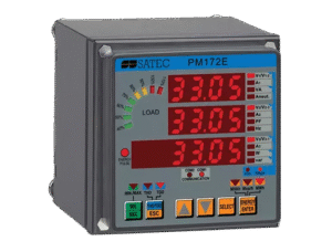
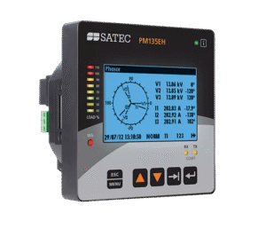
| Display | |
|---|---|
| High contrast 1.77” TFT color graphics display with configurable backlight | |
| Multi-page displays; time, instrumentation and service data | |
| Menu-driven setups | |
| Multilanguage support | |
| Real-Time Clock & Synchronization | |
|---|---|
| High-accuracy real-time clock with a lithium backup battery | |
| Clock synchronization to a UTC time reference using an IRIG-B timecode source or an IEEE 1588 PTPv2 master clock | |
| Daylight saving time shift for local time indication with configurable DST start and end time | |
| Power Supply | |
|---|---|
| 57.7-277V AC / 48-290V DC | |
| AUX 88-264V AC / 90-290V DC | |
| AUX 9-36V DC | |
| Enhanced Meter Security | |
|---|---|
| 3 levels Password security for protecting meter setups and accumulated data from unauthorized changes | |
| Mounting | |
|---|---|
| DIN Rail mount | |