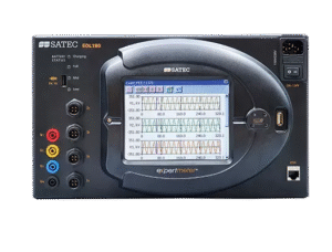
Class A (Ed. 3) Power Quality Analyzer
IEC 61000-4-30 Class A
IEEE C.37.118
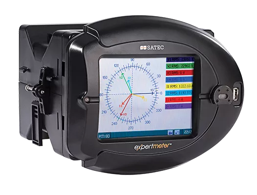
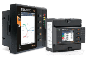
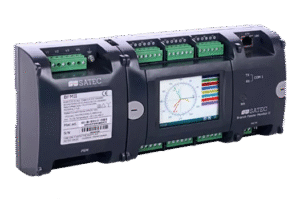
The PM180 combines multiple highly-advanced functionality in a single device, making
it a winner as a cost-effective solution.It is characterized by a unique modular design,
allowing the hot-swap of a variety of add-on cards, enabling versatile functionality.
As such, it can combine and substitute the functionality of several devices, saving costs
and space, while minimizing complexity.Learn more of the unique features of
this product and how it is the top offer for your substation.
| Accuracy | |
|---|---|
| Class 0.2S per IEC 62053-22 | |
| Class 0.2 per IEC 61557-12 | |
| Power Meter | |
|---|---|
| Power: True RMS volts, amps, power, power factor, neutral current, angles and unbalance for voltage and current, frequency, symmetrical components and many more | |
| Event and parameter data-logging | |
| Sampling frequency: up to 1024* samples per cycle | |
| Advanced Time Of Use (TOU) feature (16 Energy sources include external digital pulses, up to 4 seasons, 4 daily profiles, 8 Tariffs, flexible automatic calendar) for any complex billing scheme | |
| KYZ or KY output and LED indication for calibration and test (via optional display) | |
| Power Quality | |
|---|---|
| NMI certified for Class A, Edition 3, per IEC 61000-4-30 | |
| EN50160 / GOST 32144 monitoring, statistics & reports | |
| Event statistics complimented by waveform recording | |
| in 8 channels (4 voltage inputs, 4 current inputs) @ 256/1024 samples/cycle | |
| V-I angle, THD, TDD and K factor for Voltage and Current and up to the 63rd order harmonic. individual harmonics for V, I, P, Q | |
| irectional power harmonics (Load or Source) Inter-harmonics | |
| Including directional power harmonics (Load or Source) | |
| Inter-harmonics | |
| Disturbance Direction Detection (upstream/downstream) | |
| Flicker according to IEC 61000-4-15 | |
| Detecting transients as short as 17μs | |
| Phasor Measurement Unit (PMU) | |
|---|---|
| Time-of-Use (TOU), 8 totalization and tariff energy/demand registers x 8 tariffs, 4 seasons x 4 types of days, 8 tariff changes per day, easy programmable tariff schedule | |
| IEEE C37.118.1 3-phase V/I phasor measurements synchronized to a common UTC time reference (e.g. GPS), using an IRIG-B timecode source or an IEEE 1588 PTPv2 master clock source | |
| Expected steady-state total vector error (TVE): < 0.05% | |
| Streaming rate: 1 to 50 or 60 frames/s @ 50 or 60Hz, respectively | |
| IEEE C37.118.2 | |
| Selectable phasor type: phasor data only; positive sequence only; phase data + positive sequence | |
| Client-server UDP and TCP data transmission; spontaneous UDP data transmission over IP protocol | |
| Optional IEEE C37.118.2 frame extensions with analog data (total active, reactive and apparent power and power factor) and digital status data (up to 32 inputs) | |
| Spontaneous/unsolicited transmission of CFG-2 / CFG-3 frames. When enabled, the CFG frame is sent once before the start of transmission in unicast UDP/TCP modes and periodically every 30 seconds in multicast/spontaneous UDP mode | |
| Phasor data streaming over Ethernet using IEC 61850-9-2 multicast sampled value (SV) service with IEEE C37.118.2 compliant mapping of synchrophasor data in accordance with IEC 61850-9-2 and IEC 61850-90-5 guidelines | |
| 5 data streaming slots for continuous synchrophasor data streaming via unicast UDP or/and TCP connections | |
| Logging, Recording & Programming | |
|---|---|
| Programmable controller: up to 64 control setpoints, up to 8 conditions OR, AND, arithmetical functions logic, extensive triggers, programmable thresholds and delays, relay control, event-driven data recording | |
| Supports IEC 61131 PLC Configuration (LD, FBD) | |
| 8 fast waveform recorders: simultaneous 8-channel AC, one DC: up to 48 digital inputs in a single plot | |
| Waveform sampling rate 32, 64, 128 or 256 samples per cycle; up to 20 pre-fault cycles (2 cycles of 1024 samples per cycle or 4 cycles with 512 samples per cycle with Transient Module) | |
| Up to 3.5 min. of continuous waveform recording | |
| 1-ms resolution for digital inputs | |
| 16 fast Data Recorders (16 parameters on each data log): From ½ cycle RMS to 2 hour RMS envelopes; up to 20 pre/post-fault cycles; programmable data logs on a periodic basis and on internal or external trigger | |
| ½-cycle response time | |
| 32 digital internal counters | |
| 16 internal programmable timers (½ cycle to 24 hours) | |
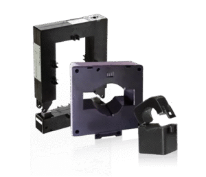
| Variable Current Inputs | |
|---|---|
| 5A | |
| 1A | |
| HACS: special 40mA inputs for SATEC’s High Accuracy Current Sensors | |
| CS1S: specific inputs for 100A split-core HACS, calibrated to 5A | |
| CS1H: specific inputs for 100A HACS handheld current clamps, calibrated to 5A | |
| 3V AC: inputs for generic current clamps (Rogowski) | |
| 200A @ Digital Fault Recorder module | |
| Built-in I/O | |
|---|---|
| 2 Digital Outputs: 3A/250 VAC; 3A/30 VDC; 2 contacts (SPST Form A) | |
| 2 Digital Inputs: (dry contact; 15V Internal power supply) | |
| Voltage Measurement Inputs | |
|---|---|
| Available options: |
|
| 120V AC Nominal voltage | |
| 690V AC Nominal voltage | |
| Operating range |
|
| Wide range application up to 828V AC | |
| 5th AC/DC voltage input: |
|
| monitoring substation battery (up to 300V DC) |
| Communication interfaces | |
|---|---|
| Built-in | |
| RS-485 | |
| RS-232/422 | |
| Optional/additional: (1 per device): | |
| ETH 10/100Base-T | |
| PROFIBUS | |
| 2G/3G/4G modem | |
| Additional I/O | |
|---|---|
| 4 Digital I/O | |
| 2 Digital Inputs + 2 Digital Outputs | |
| 2 Analog Inputs available rating: |
|
| ±1mA | |
| 0-20mA | |
| 0-1mA | |
| 4-20mA | |
| 2 Analog Outputs available rating: |
|
| ±1mA | |
| 0-20mA | |
| 0-1mA | |
| 4-20mA | |
| 0-5mA | |
| ±5mA | |
| Programmable Logical Controller | |
|---|---|
| Embedded programmable controller | |
| 16 control set points; programmable thresholds and delays | |
| Relay output control (for alarm and protection) | |
| ½-cycle response time | |
| Display Options: | |
|---|---|
| Transducer version: no display. Installed on DIN-rail | |
| Transducer version: no display. Installed on DIN-rail | |
| LED Display: 3 line ultra bright LED display | |
| Real-Time Clock & Synchronization | |
|---|---|
| Real-Time Clock with maximum 5 seconds drift per month @ 25°C | |
| Provides 1 msec time resolution via IRIG-B time code input or satellite clock for common time base (requires IRIG-B module) | |
| As an SNTP client, it can accept periodic synchronization of the meter clock from an SNTP server | |
| Time sync from digital input with 1ms accuracy | |
| Communication Protocols | |
|---|---|
| Modbus | |
| ASCII | |
| DNP3.0 | |
| Profibus | |
| Power Supply | |
|---|---|
| 9.6-19V DC | |
| 19-37V DC | |
| 37-72V DC | |
| Enhanced Meter Security | |
|---|---|
| 3 levels Password security for protecting meter setups and accumulated data from unauthorized changes | |
| Defining up to 20 users in different access levels | |
| Extra-complex password is required | |
| Access and configuration log is automatically and continuously recorded, documenting all user activity | |
| Mounting | |
|---|---|
| 19″ rack installation | |
| DIN Rail mount | |
| panel mount | |